
OK, that will be possible to mod to full PICkit 2 compatibility.
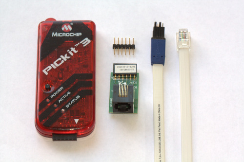
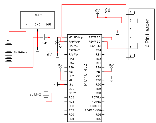
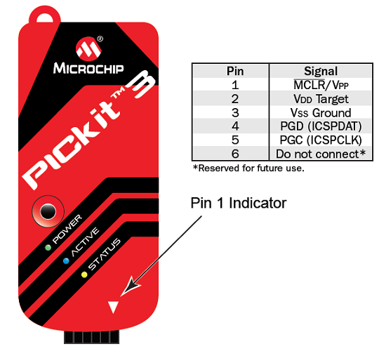
Pickit 3 pinout Patch#
Post good closeup photos of both sides of your programmer's PCB, and we may well be able to suggest a circuit you can build on protoboard to upgrade it to full PICkit 2 hardware compatibility, and the points you'll need to patch into.
Pickit 3 pinout mods#
Thus you can be 99.9% sure your mods are good before you even have to connect to a target chip. If you want to check the ICSP lines as inputs or check the AUX as outputs, use Tools: Logic tool. It also lets you check Vdd and PGC, PGD outputs. dialog to check if your programmer is capable of variable Vpp, which it sets depending on the device family selected. You can use the Pickit 2 utility Tools: Troubleshoot. Its preferable to figure out if you can mod the programmer to isolate the feed to L1 from the programmer's 5V target supply and re-connect it (with associated decoupling caps) to an appropriate regulated supply or even target Vdd if the target is externally powered. That will do nicely for PGC, PGD and AUX,using any 'jellybean' PNP you have handy, with another, diode connected (join base and collector, and call it the cathode) replacing D1 to provide the base bias voltage. The top half is the clamping circuit which is a PNP transistor for each line with its emitter to the line, collector to ground and its base held one diode drop below target Vdd. See FIGURE B-2: PICkit 2 SCHEMATIC DIAGRAM (PAGE 2 OF 2) in the PICkit 2 user guide.
Pickit 3 pinout generator#
Its also possible to FUBAR the Vpp generator by a poor choice of inductor with too high DC resistance. If you run into issues, note that many clones have problems with poor choice of substitute OPAMP U2 in the target Vdd regulator which *must* be true RRIO, and handle a supply voltage range of 4.5V to 6V, P-MOSFET Q1, the Vdd pass transistor which must have a low Vgs threshold, and the Vdd switch dual MOSFET U5 which again needs low threshold voltages, and a low enough Vds_on for its PMOS half to avoid excessive voltage drop under load.

However I would suggest taking the opportunity to fully upgrade your clone for variable Vdd support. For non-HV programmed PICs you'll need another instance of the per line part of the clamping circuit to limit Vpp/MCLR to 3.3V. If your PICkit 2 clone omits the clamping circuit for reduced target voltage support, it can be added externally, copying it from the PICkit 2 schematic. Assuming 'fchk' is correct and that PIC24 doesn't use HV programming (I haven't checked its datasheet), then (2) is irrelevant, (but see clamping below). If your PICkit 2 clone doesn't have 3.3V Vdd support don't connect PICkit 2 target Vdd to the target ICSP interface. If the target is externally powered, (1) is irreverent.


The PIC24FJ256GB106 is supported for debugging and programming with a PICkit 2 under MPLAB v8.92, or with the PICkit 2 standalone utility v2.61 so it depends on how accurately your DIY clone follows the genuine PICkit 2 schematic.


 0 kommentar(er)
